General advantages explained-MAIN features explained

Find explanation below (numbers matters)
1. Standard soldering power pads
These solder pads are your first option to solder power input cables/connectors to LED strips. These solder pads do always contain our special SYSCON connecting throughout holes (described bellow). Their siye and shape match with other pads on the same LED strip. Surface treatment is ENIG, which means it is gold treated, to maintain perfect solderability even in harsh environment.
2. Alternative soldering power pads
These solder pads are great when additional devices / LED strips should be powered from the end of the LED line, suitable as standard power pads after shortening , or used as alternative soldering pads where soldering cables on far end will be too close to ALUminium profile (causing short-circuit)
3. Standard cutting line
Your first choice to cut the LED strip to desired length (normally marked with sign of "scissors"-The very first on the picture) In case your LED line is slightly longer than your ALU profile, most of our special LED strips MASTER, do contain special place to cut the last segment to even smaller size. Yes, you can cut the segment to smaller size (from the end where is no IC driver) read more about this special place bellow (4. and 5. point)
4. Alternative cut line (shortening cut-line)
In case you LED strip is slightly longer than your ALU profile, you can cut the last segment to smaller size (only from one end - only 1 part where IC driver is present will be lit) Normally most of our designs do contain options to shorten the last segment from : 4SAUNA (3LED design ) to 2LEDs, and most of our other designs to as low as 4LEDs. Be aware of shortening the last segment - this last segment might perform slightly differently in some scenarios. Most situations where this is issue is :
- analogue dimming - when powering off the installation, Voltage on power source will be gradually lowered in next few seconds, and this segment might for this short duration be more visible than others. This is only visible when powering off the device, or analogue dimmers will be used. Always use PWM dimming system.
- standby state (power supply or dimming controllers) - even when power supply or dimming controller is dimmed to 0, or to OFF state, some tiny current might still be present. This tiny current might be sufficient to power up this "shortened segment" to very small brightness, thus might be lit and visible even when all other segments will be off. This is only visible for specific power supplies, or controllers, when digitally powered off, or 0% brightness is set.
- Using LED strips bellow its Minimum allowed voltage - (commonly found when super long and thin wires are used, thus Voltage drop on this portion of LED strip is lower than parameter "Min. allowed voltage". Avoid using very long and thin power wires, which could improove visibility of this behaviour. If you find it in your scenario,, you can be sure, your LED strip at this area is powered bellow 100%.
5. SP end-of-line solder point (after shortening)
This solder point is important - is meant to apply small amount of solder/tin with soldering station at the place most close to the place you have shortened the last segment (used only when segment will be cut to "smaller non-standard size" at the place "4.alternative cut line".
6. SYSCON throughout holes (1.27mm pitch)
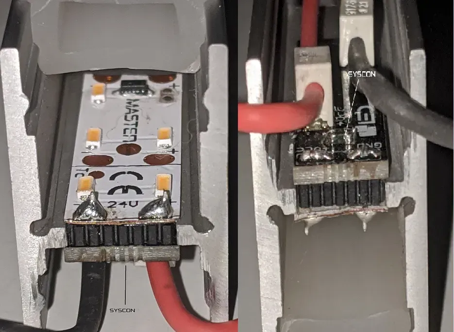
This tiny but important feature allows for two great benefits :
A. while soldering the tin will fill up the hole and will provide maximum current path and mechanical rigidity at this place
B. piercing the bottom mask with tiny needle, will allow a systematic miniature connector (SYSCON-INTERLINI) to be installed in the body of luminiare where this LED strip is used. (connector will allow the LED strip to be powered from connecting system where IDC connectors will be cut through insulation to the very thick interconnecting wires , hidden in back hollow inside the ALU profile. This allows you to use the LED strips for systematic installation of "ready made luminaires" with great current path (upto 30A) reaching anything from 25m (Superpower) upto 300m (Longrun).
7. High Quality LEDs
Only quality LEDs can perform and reach great lifetime, IES/LDT plugins, luminous flux, corrosion resistivity. We use mainly OSRAM LEDs, LumiLEDs, Seoul Semiconductor LEDs, and for RGB applications Brightec LEDs. Check our Colours
So cheap LEDs are cheap because their construction was "cheated on materials, design or details, some of them are enclosed here :
- inner reflector - normally made out of silver (general lighting) or gold (professional range, with great corrsion resistance to H2S, salt enviroment and others )...cheap LEDs use Aluminium, with almost no corrosion resitance (as it degrades, light is simply not "reflected" through epitax layer and is absorbed by this "degraded reflector"
- bonding wire - all professional manufacturers use gold for this important inner wire, if cheap LED producers can lower their prices, this is the point : aluminium or copper wires, which does degrade fast and melts in much lower working currents, but are much cheaper..
- thermall substrate - affecting thermal resistance - important parameter, when it comes to dissipating the heat generated from LEDs....the lower the number, the faster the heat generated from LED is penetrated to substrate and to PCB, which will cool down the LEDs....thus the LED PN junction while working can reach much lower temperature and prolong its lifetime several times.
-
BINning - most professional producers do BIN their LEDs on 3 main parameters : Lm flux (Lm), CCT (K), Forward voltage (V). The more precisely you BIN (test and group similar LEDs together) the more "combinations of these 3 parameters" you will have on stock...1 product can have as many as 2000 individual selection groups (BINs)....cheap manufacturers dont BIN at all or don't BIN precisely enough, so their products don't have precise Lm flux, or CCT can be anywhere +-500K (sometimes with pink or greenish tint which is not part of MacAdams diagram defining white spectrum) or its forward voltages will vary so much that it will affect their lifetime (when connected in parallel)
Simply if you produce 1000 000 warm white LEDs, and you BIN it (separate it) into - 5 brightness bins
- 4 forward voltage bins
- 7 chromaticity bins
then you as producer can end up (on average) with 7142 identical LEDs with same BINing combinations, which is not very interesting for any client to buy. Instead, if you do not BIN it at all, you would end up with 1000 000 LEDs immediately for selling...so BINing is really complicating things up for producers, on the other hand it is the only correct way how quality product can be delivered to build quality final product.
...and many more, feel free if you are interested in more details. Contact us
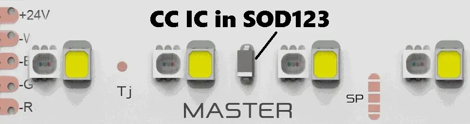
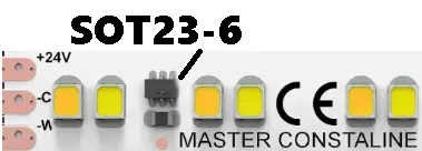
8. Constant current driver CC IC
LED products without constant current regulation are reaching lifetime 1000-15 000Hours, it is very rare to reach higher lifetime above 30 000Hours (L70B50). It is matter of physics and it is not to argue about. It's a fact which we can discuss for hours, once you will understand all the details there is no other result just our.
On the opposite side, reaching great lifetime with CC IC design (all our MASTER LED strip designs contain CC IC) is easy, as CC IC is dedicated current regulator protecting the LEDs from having different current than it is set - it is active regulator taking care of only the few LEDs which are in series in single LED strip segment.
Most CC IC or regulators have the following features :
- it regulates current to fixed value, no matter the voltage is 22V, 24V or 28V, it will always be as it is set.
- all excessive heat is dissipated on this device, thus protecting LEDs from overpower
- CC ICs normally have a NTC thermall coeficient, meaning if the temperature rises, the curent very slightly drops, protecting the LEDs from overheating
- CC IC is imune to large range of voltage drops, so to dimm it use always PWM system. PWM is Pulse Width Modulation, which is always and immediately all over the length of each LED strip immediately, not like analogue dimming where different voltage is different on every part of LED strip due to internal resistance.
CC IC types we use :
SOD123 package |
|
SOT23-6 package |
|
our special newest scalable design : |
9. Current setting device
This device sets current of the CC IC driver, In case it is missing or is not solder correctly, current will drop to 10mA.
10. ESD protection device
Electro Static Discharge device eliminates the high voltage peaks which could cause LEDs fail when touched the power wires.
ESD is often found when :
- soldering station is not ESD safe (special antistatic conditions and "ESD safe" sign is required)
- person touching the LED strip did not touch (discharged) to grounded metal structure (a grounding wrist bands are great while manipulating the LEDs)
- be aware that any move on certain materials (carpets, laminate flooring, scissor lift machines, etc) are producing high ESD discharge
11. Flexible circuit board
Thin in construction, based on high temperature resistive core materials, yet with thick and highly pure copper paths are great details for quality FCB. High flexibility allows for great bending parameters, thin structure allows for better heat dissipation.
12. Heat resistant mask
Quality and highly reflective solder mask can greatly enhance final light output/scattering ) when installed in ALU profile. High temperature resistivity can allow certain products to be used in as high temperatures as 100°C (SAUNAs) or at direct sunlight permanently without yellowing (some tipes of silk screened masks can degrade/crack/yellow under harsh enviroment).
MAIN Design features - Portfolio overview

D1. Polyimide heat resistant core
Polyimide is very robust and heat resistant material, able to withstand upto 360°C, has perfect chemical resistivity, low water absorption. Polyimide used in core of the FCBs is special kind of Nylon, providing best all in one features for core your MASTER LED strip. Most producers use Polyamide, which has higher elongation.
D2. Heat conductive and resistant double sided tape
Most of our standard products use genuine 3M Heat resistant tape, which sticks almost to everything. To provide even better cooling for SuperPOWER LED strips which can have 30W or higher, these LED strips are supplied with special heat-conductive tape with ceramic powder inside, which helps to transfer the heat from LED and FCB base to ALU profile even better.
D3. Thin TOP copper layer for flexibility
Most LED strips producers produce teh FCB in easy way for them :
- If 1oz copper thickness will be used on both top and bottom layers, flexibility will be great but power energy transfer over distance will be too weak)
- if 2oz copper thickness will be used on both top and bottom layers, flexibility will be very bad (LEDs could break upon strip bending) but power energy transfer will be great.
We use not easy to produce, but great from both worlds : 2oz on bottom for great power transfer over longer distance + 1oz on top for great flexibility.
D4. Thick bottom copper layer for energy transport with minimal loss and great heat management
Thickness of bottom layer in LED strips do have biggest impact on quick cooling and great power transfer over long distance with minimum losses. Using bottom layer 2oz pure copper, is crucial to get perfect lengths, parameters, etc. You can feel the thickness difference in hand, most producers use cheaper version with 1oz copper thickness.
D5. Axially shifted LEDs
Some designs have axially shifted LEDs on purpose. Reason is simple and very interesting :
Shifting the LEDs 1mm aside doesnt make any difference for light effects if standard diffusers are used. However if Linear optics are used , even if symetric optic is used, it creates slight angle shift to the side, creating wallwashing effect. It minimizes the glare for users from one side , and it pushes the ligth asymerically creating wall washing effect. You can find this detail for example in our MASTER-HD-POWER design.
D6. LEDs grouped together for better colour mixing
Grouping RGB and White LEDs together can significantly improve visual consistency and colour mixing quality. As always, there is tiny trade-off. Such design is not very suitable for power applications, as heat generated by White LED can impact and colour shift RGB LED spectrum, which can be sometimes very heat sensitive. So mainly in power applications, we tend not to group White and RGB LEDs together, to keep RGB LEDs cooler and improve its lifetime and colour stability. Such example can be found at MASTER-CONSTALINE-84RGBW and MASTER-CONSTALINE-28RGBW
D7. LEDs evenly distributed - better heat management and smaller colour shift while mixing
As desicribed in D6, sometimes we do design multicolour LED strips which do not have RGB and white LED grouped together. This can be on purpose, especially for designs which do work with higher powers and so with higher heat. Having all LEDs evenly distributed with same spaces next to each other, can decrease optical colour mixing, but it increases colour stability over time. Such example is MASTER-42RGBW
General questions & Know How
Which LEDs in what package and why we use them?
Our general priorities :
- all LEDs must be in compatible package, so any LED can be assembled on any design with identical FCB footprint (now we have 42 colours)
- all LEDs used must be well overrated, so even very powerfull product will use LEDs in their lower half of "max. current limit"
- stock availability for prompt custom assembly (most designs are stocked in standard options, but we keep most of our stock unassembled to mix and match exact combination of product for any project or any client.
Monochromatic LEDs :
- All LEDs must be in 2835 or 3030 package, so it can be exchaged for any kind. OK, but isn't 2835 package old technology? No, as package size doesn't tell about LED generation or technology.
- All LEDs must be stocked with as low Forward voltage BINs as possible
- All LEDs must be marked with their BINs, they can NEVER be mixed 2 or more BINs on any product. Each product is well marked with version of PCB and BIN of LEDs used.
- Various LED spectral properties to be chosen from, see our colour chart and our Coding system to identify what LED manufacturer is used, find appropriate LED manufacturer datasheets, etc.
RGB LEDs :
All LEDs used are in 3030 SMD package, slight frost optics for better colour mixing. Its max. current limit is 180mA, but as RGB colours are used at lower powers generally, we specially ask producer to BIN them on 30mA for us, so all colours will match perfectly.
RGB+W :
Sometimes colour mixing is the most important detail if using multicolour designs. Having single LED in RGBW is from our point of view not very suitable even many people do prefer it. Having single LED with all 4 colours inside provides better colour mixing, but everything else is worst : White LED is normally hardly available in CRI90+, definitely not with special spectral properties as SUNLIKE, Crispcolor, Horticulture, etc. Another issue is sometimes RGB doesnt have to be powerfull , but white has to be powerfull to create main power lighting, so having such overrated LEDs RGBW will be nightmare to match colours, as the BINs normally are rated at half the maximum current, which can be much higher than set current. That is reason why we use dedicated White LED to be in 2835 SMD package , which can be chosen with any of 42 spectral properties and RGB LED in SMD 3030 package, which has 150mA max. limit, yet custom BINned to only 30mA to keep perfect colour consistency.
Marks :
A. Polarity / Voltage marks
B. TJ thermal measuring point
C. Quality approved MASTER logo
D. Made in EU logo
E. Osram LEDs included logo
F. Made in EU logo
G. CE Logo
H. WEE logo
I. ESD logo